Challenges of migrating network virtual appliances
The integration of stateful appliances, such as firewalls, in the network has historically been dependent on the network topology. In order to guarantee that traffic traverses the stateful appliances, these are deployed so that they are the only path that traffic can follow between two or more networks. To guarantee an acceptable level of resiliency, redundant appliances are deployed. The routing involved in providing this redundancy, while guaranteeing traffic symmetry, is very complex, implementing a policy in which only select traffic flows are routed through the appliances results in topology changes and even more involved routing.
Moving these services to the cloud as Network Virtual Appliances (NVAs) presents an opportunity to significantly simplify the networking required to maintain resiliency, fast failover, and traffic symmetry while providing the ability to insert network appliances for select flows and scale the NVAs elastically.
A well known deployment pattern used in cloud is to deploy the NVAs between two VPCs, so that they are the only path between a trusted and untrusted network. This scenario is depicted in Figure 1 and although the use of load balancers does address the resiliency and traffic symmetry concerns of this deployment, the solution is still topology dependent and provides little flexibility to add or remove NVAs selectively. By leveraging load balancing and policy-based routing, Google Cloud offers a topology-independent, policy-based mechanism for inserting network virtual appliances (NVAs) into your cloud network.
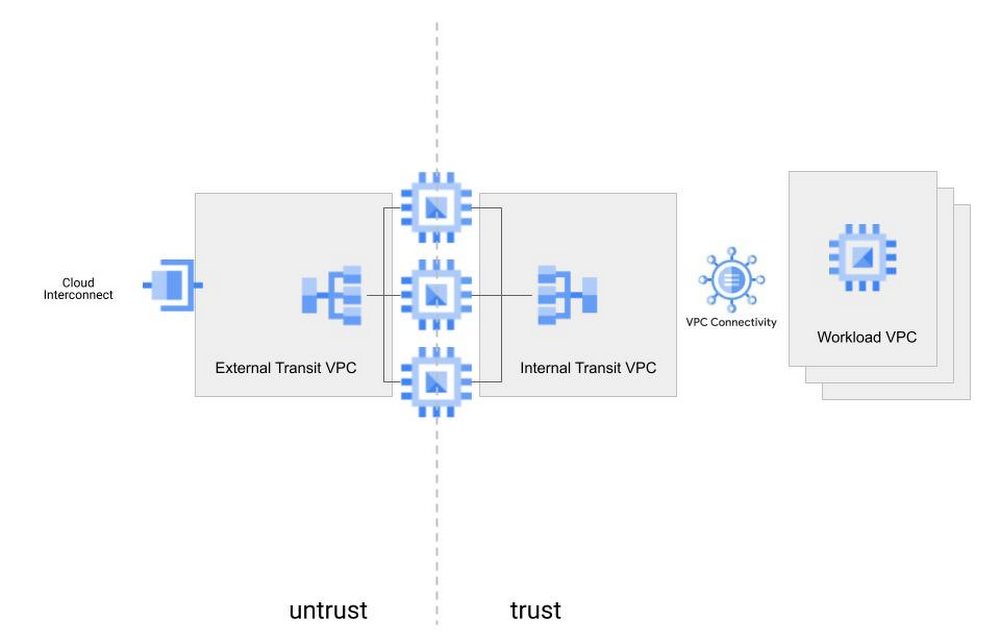
By leveraging load balancing and policy-based routing, Google Cloud offers a topology-independent, policy-based mechanism for inserting network virtual appliances (NVAs) into your cloud network. With this approach, NVAs can be inserted for specific flows, based on policy, without requiring any particular VPC topology configuration.
Solution Overview
Inserting NVAs with Policy Based Routes involves two main functional components:
-
NVA resiliency
-
Traffic steering
The solution leverages internal TCP/UDP load balancers to group and provide resilience to NVAs. The solution also uses policy-based routing to steer traffic to the NVAs. Different NVAs may be selected from Google Cloud’s ecosystem of partners. Figure 2 illustrates the high level view of the solution.
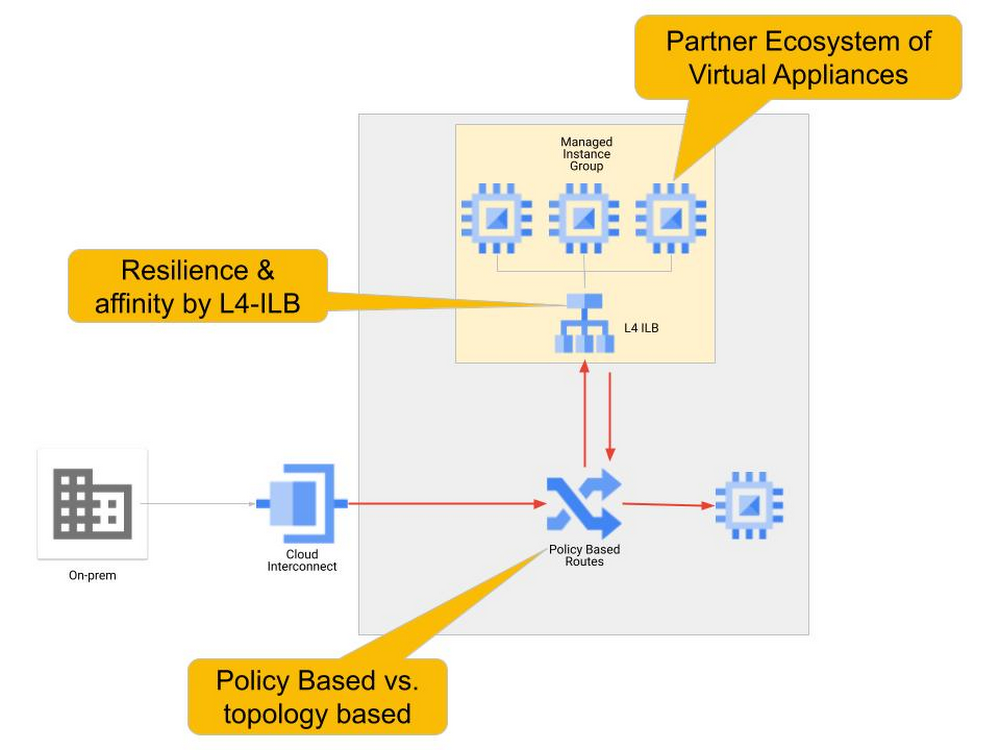
To enable resiliency for NVAs, the NVAs are deployed in a managed instance group (MIG) as the backend to an internal TCP/UDP load balancer. NVAs are front-ended with an internal TCP/UDP load balancer to enable appliance redundancy, autoscaling for elastic capacity and flow symmetry to support stateful bi-directional traffic processing. With the Google Cloud NVA Insertion solution, networking for appliance redundancy is greatly simplified and the NVAs are abstracted into an easily referenceable load balancer front-end.
With the NVAs grouped and abstracted, the next task is to steer traffic to the load balanced group of NVAs. Policy-based routes, which take precedence over other routes in the VPC, steer traffic based on the destination and source of the traffic. You can selectively place policy-based routes at different places in the network to steer traffic through specific endpoints. Figure 3 illustrates the resulting multi-stage routing model, which allows the granular definition of very specific traffic paths for very specific connectivity flows. Each end-point in the fabric will have a different set of routes for the same destination, effectively producing multiple stages in the routing decision.

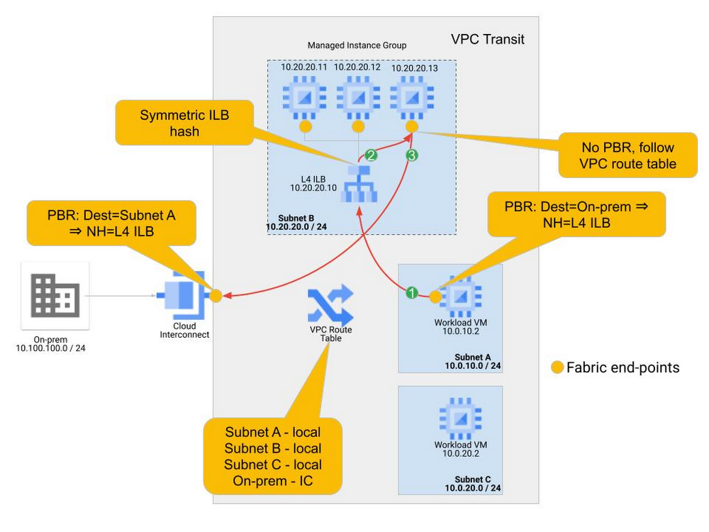
The following concrete example illustrates the traffic steering behavior and policy. In this example a single VPC hosts the workload VMs and connects to an on-premises facility. The traffic between on-premises and the workloads in Subnet A must be inspected by an NVA firewall. A cluster of 3 firewall NVAs are deployed in a managed instance group. Figure 4 illustrates this example.
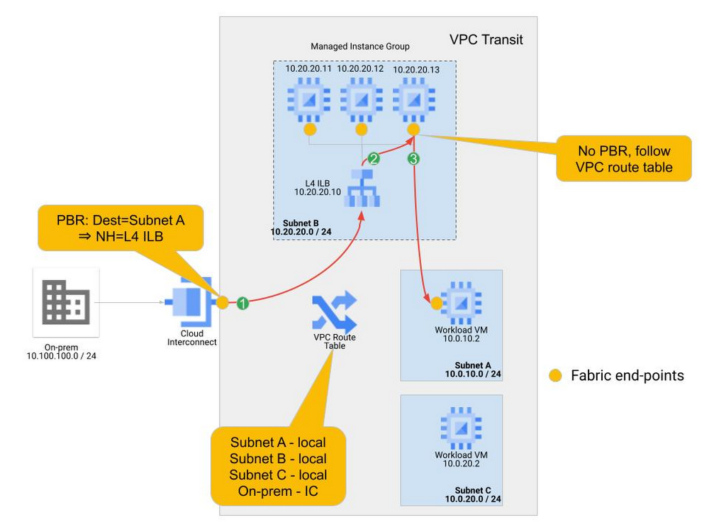
In the example, traffic from on-premises (source address in 10.100.100.0/24) is sending traffic to the Workload VM at 10.0.10.2 in Subnet A. Normally, the traffic would come into the VPC network over the interconnect attachment and follow the direct route in the VPC table to the Workload VM. In this example, we have written a policy route and applied it to the regional interconnect, so that the traffic is sent to the internal TCP/UDP load balancer instead of following the VPC route table. Multi-stage routing and service insertion takes place as follows:
-
Traffic arriving at the Cloud Interconnect connection is checked to see if its IP source and destination match a policy-based route. In our example, the policy-based route match indicates that the next hop should be the internal TCP/UDP load balancer (10.20.20.10). Traffic is sent to the internal TCP/UDP load balancer front-end. Note that this policy-based route is applied only to traffic arriving on the Interconnect and no other end-points in the network.
-
The internal TCP/UDP load balancer receives the traffic, evaluates the hash of source and destination information, and sends the traffic to one of the NVA Instances in the backend.
-
The NVA processes the traffic and returns it out the same interface. A new routing lookup must be performed as this traffic is “re-entering” the network fabric. The NVA end-points do not have a policy-based routing applied to them, so they follow the route on the VPC route table, which takes the traffic directly to its destination.
As you can see in this example, multi-stage routing is achieved by applying policy-based routings at select end-points in the network. Policy-based routes enable this traffic redirection within a single VPC, which allows the insertion of NVAs like firewalls without requiring a specific topology or multiple VPCs.
The policy can be as selective as desired. In this example Subnet C is not part of the policy so traffic destined to subnet C is not steered through the NVAs.
The return path behaves very similarly. A policy-based route for on-premises destinations is applied only to the workloads for which firewalling is wanted, which are the workloads in Subnet A (10.0.10.0/24) in this example. Network tags can be used to assign policy-based routes to only specific instances. And the symmetric hashing in the load balancer guarantees that the return traffic goes through the same NVA as the ingress traffic. The return path packet flow is illustrated in Figure 5.
-
Traffic from 10.0.10.2 destined to the on-premises prefixes (10.100.100.0/24) matches the policy-based route applied to the workload VM. Traffic is sent to the internal TCP/UDP load balancer front-end.
-
The internal TCP/UDP load balancer hashes symmetrically, so the same NVA that was chosen for the ingress traffic is chosen for the egress traffic.
-
The NVA processes the traffic and returns it to the cloud network fabric. Since there are no policy routes applied to the NVA, the route to on-premises in the VPC route table is followed.
On-premises routes are learned dynamically. One simple measure to avoid having to update the policy-based routing policy for the return traffic is to use a 0/0 destination in the policy-based routing policy. Keep in mind that this would send all traffic sourced from the instances where this policy-based route is applied to the internal TCP/UDP load balancer. Policy-based routing takes precedence over all routes in the VPC route table, including subnet routes. This is useful if the desire is to have all flows, including VM-to-VM flows, be steered through the NVAs. A policy-based route matching on 0/0 destinations and applied to all VMs in subnet A and subnet C would guarantee that all VM-to-VM communication (inter and intra subnet) is steered through the NVAs. If VM-to-VM communication (East-West) through the NVAs is not desirable, the policy-based routing policy should match the on-premises prefixes or a covering prefix that summarizes the on-premises space.
The same behavior can be used in different topologies. We can easily expand our example to a multi-VPC topology in which the workloads are in spoke VPCs connected to the transit VPC via VPC Network Peering. For ingress traffic the behavior does not change, for the return path we recommend the use of static routes, rather than policy-based routes for the route override that must be applied to the relevant instances. Figure 6 illustrates this scenario.
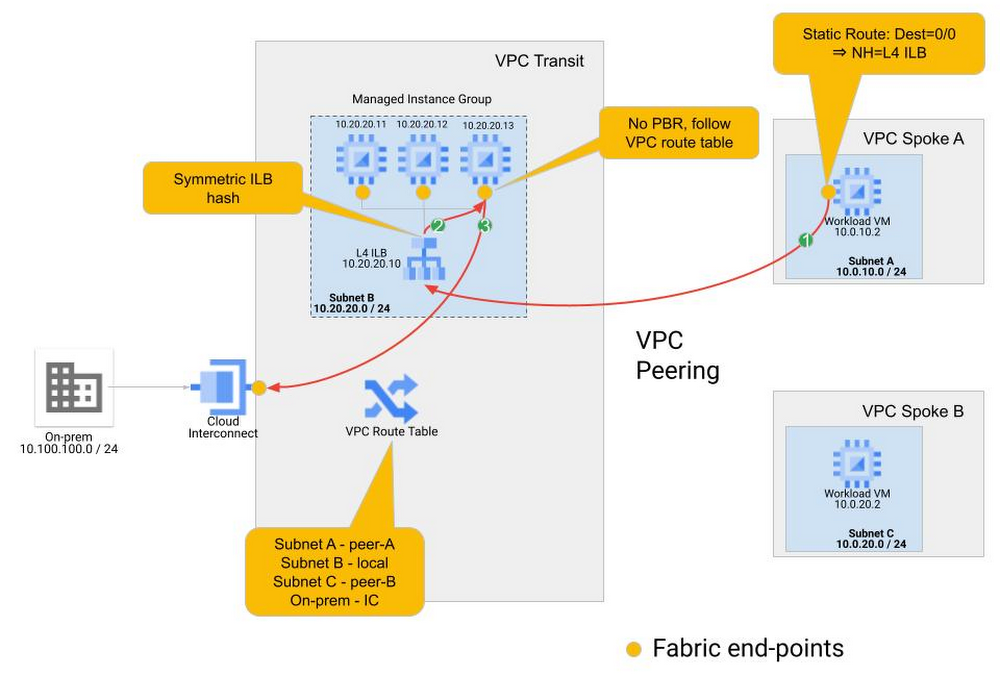
By using static routes for the return policy, we can use a default (0/0) match that abstracts any variability in the on-premises prefix space. We must also ensure that the dynamic routes learned from the on-premises locations are not propagated over the VPC peering. Thus, without specific routes to on-premises, the workloads in the spoke VPCs will use the 0/0 static routes that point to the internal TCP/UDP load balancer in the Transit VPC, effectively providing a return path via the NVAs. This configuration does not steer intra-VPC VM-to-VM traffic to the NVAs as static routes do not take priority over the subnet routes for the local subnets in the VPC route table. The use of 0/0 static routes at the spokes also steers all internet-bound traffic to the NVAs.
Using 0/0 as the destination to match for the static route could potentially enable communication between spoke VPCs. This configuration does not steer intra-VPC VM-to-VM traffic to the NVAs as static routes do not take priority over the subnet routes for the local subnets in the VPC route table, but spoke-to-spoke traffic would be steered to the NVAs. Spoke-to-spoke traffic routed to the NVAs would have to be explicitly allowed by the NVAs to complete the communication. This works as long as there is only one group of NVAs in the solution. Traffic asymmetry will be a problem once there are multiple NVA MIGs at play, like in the multi-regional case. With enough effort a policy to enable spoke-to-spoke communications through multiple NVA groups can be designed and deployed, but we don’t recommend pursuing this.
Regional Considerations
Multiple regions will call for multiple NVA groups, usually one per region. We recommend that the NVA instance group you use aligns with the cloud hosted Workloads involved in the flows. We refer to this concept as regional affinity, and our recommendation is to create affinity between the NVA Instance Groups and workloads in the same regions. For flows that involve workloads in region A, the redirection policy should steer traffic to the NVA instance group in region A. Thus, for North-South flows, the inbound policy to be applied at the Interconnects matches the workload destination subnets and include as the next hop the internal TCP/UDP load balancer that is in the same region as the destination subnet.
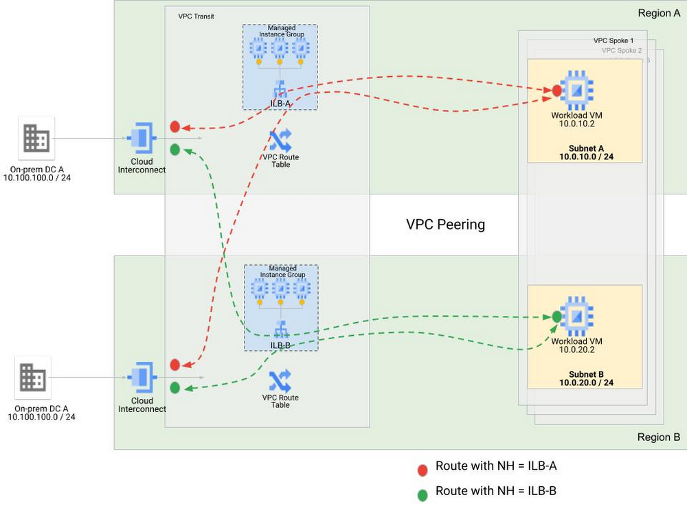
For North-south traffic flows: Traffic that enters Google Cloud via an interconnect connection in one region to access workloads in a different region will be redirected to the NVA instance group in the destination region, the VIP for the internal TCP/UDP load balancer for this NVA Instance Group is reachable using the information in the VPC routing table. Global access on the internal TCP/UDP load balancers must be enabled so that clients in other regions can reach the internal TCP/UDP load balancers. The return traffic would rely on the VPC routing table to get from the service nodes to the customer premises , which requires global dynamic routing to be enabled in the VPC for the egress routes to be known across regions. The return traffic would be routed to the load balancer that is local to the replying workload.
The resiliency profile of this solution is anchored around the high resiliency that the distribution of the MIGs and internal TCP/UDP load balancer front-ends across zones provides within a region. Since we use static policies in policy-based routing, cross-region failover in case of the failure of an entire NVA instance group is not an option.
Special thanks to Babi Seal, Product Manager for Load Balancing and Cloud Networking, Zach Seils Networking Specialist Customer Engineer for Google Cloud and Osvaldo Costa, Networking Specialist Customer Engineer for Google Cloud